- 1Obtain a durable lumber suitable for the project. The project in the photos uses pressure treated southern yellow pine, recycled from an old deck. Choosing premium lumber, or even a synthetic material made from recycled plastics will afford a higher quality finished project.
- 14 - 2x6 72 inches (183 cm) long.
- 5 - 2X4 30 inches (76,2 cm) long.
- 3 lbs. 12d (3 1/2 inch) hot dipped galvanized nails. (Substitute 3 1/2 inch exterior (deck) screws for greater strength)
- 2Cut:
- Cut 12 2X6 boards 72 inches (183 cm) long. 6 til bordplate. 2 til seat rails. 4 til sitteplate.
- Cut 3 2X4 boards, 30 inches (76,2 cm) from long point to long point, with 45 degree angles on each end.
- Cut 4 2X6 boards 35 inches (88,9 cm) long from long point to short point, with a 25 degree angle on each end. Til bein.
- Note that you will also have to cut the diagonal bracing underneath the table top, but it is best to scribe this board to fit after the rest of the top is fastened together.
- 3Lay out the top boards on sawhorses, setting them so the best side (least knots, cracks, etc) is down, since this will be the bottom of the table top.
Lumber arranged on the sawhorses, best side down.
- 4Nail, spaced 4 inches (10 cm) from either end and the third centered between the ends the 2X4 boards with the 45 degree angle cuts to the bottom of the table top. Toenail these to hold them in position until the table is flipped over, when you can finish nailing the top.
- 5Position the 35 inch (88,9 cm) 2X6s so they are centered over the short point of the table top end rails as shown in the photo, and nail them securely to the rails.
- 6Measure up (down from the top when the table is flipped) 17 inches (43,2 cm). Drive a nail into the leg at this mark, half way to the head. This will support the seat rails, which you will install next.
- 7Center the seat rails (also 2X6 72 inches - 183 cm - long), centered between the inverted table legs, resting on the nails you have driven in at 17 inches. Nail these through into the legs.
- 8Mark the centers of both the table top middle rail and the seat rails. Scribe a 2X4 to fit diagonally between these marks, as shown in the photo. Cut these, and nail them securely into place.
- 9Invert your table so it is now standing on its legs. Lay your seat boards (again, 2X6s, 72 inches - 183 cm - long, on the seat rails that should be sticking out from beneath the table on each side. You will want to try them out for size, shifting them in or out along the rail until they are comfortable for you. When you have these rails in a desirable position, mark the location of the outer seat board, remove them, and saw a 45 degree angle on the rail so none of it will protrude from beneath the seats.
- 10Reposition the seat boards and nail them off. Drive nails through the table top boards into their rails to finish securing them.
- 11Cut the corners of the table top at a 45 degree angle about 2 inches (5 cm) from the corners so they are rounded, to make it less likely anyone will bump into them.
- 12Sand and finish the table as you want. You can use a silicone waterproofing sealer, an exterior polyurethane (many so-called polyurethane products actually degrade in ultraviolet light), or a semitransparent exterior wood stain for this purpose.
- 13Set your table up in a shady spot and enjoy it.
Monday, March 14, 2011
How to Build a BBQ Table
Steps


Tools list
Aviation Snips (yellow handle – straight)
Aviation snips are used in applications which include HVAC installation and repair; exterior remodeling industry (roofing, siding, gutter, and down spout installation and repair; metal building construction; RV/motor home/trailer manufacturing; auto body repair; and general sheet metal cutting
Calculator (Construction Master Pro)
Carpenter’s Pencil
The shape of a carpenter's pencil prevents it from rolling, even when placed on a steep sloping roof. The most popular shape seems to be a flat, octagonal style. And the lead must be strong enough to make a heavy mark and to withstand the stresses of carpentry, which frequently requires marking on very coarse surfaces. The leads are usually wide and flat.
Chalk Line (Blue and Red)-
A chalk line or chalk box is a tool for marking long, straight lines on relatively flat surfaces, much farther than is practical by hand or with a strightedge.
It is an important tool in constraction and carpentry, the working of timber in a rough and unplaned state, as it does not require the timber to have a straight or squared edge formed onto it beforehand.

 Ear Protection (reusable ear plugs)-Earmuffs are objects designed to cover a person's ears for protection. They consist of a thermoplastic or metal head-band, that fits over the top of the head, and a pad at each end, to cover the external ears.
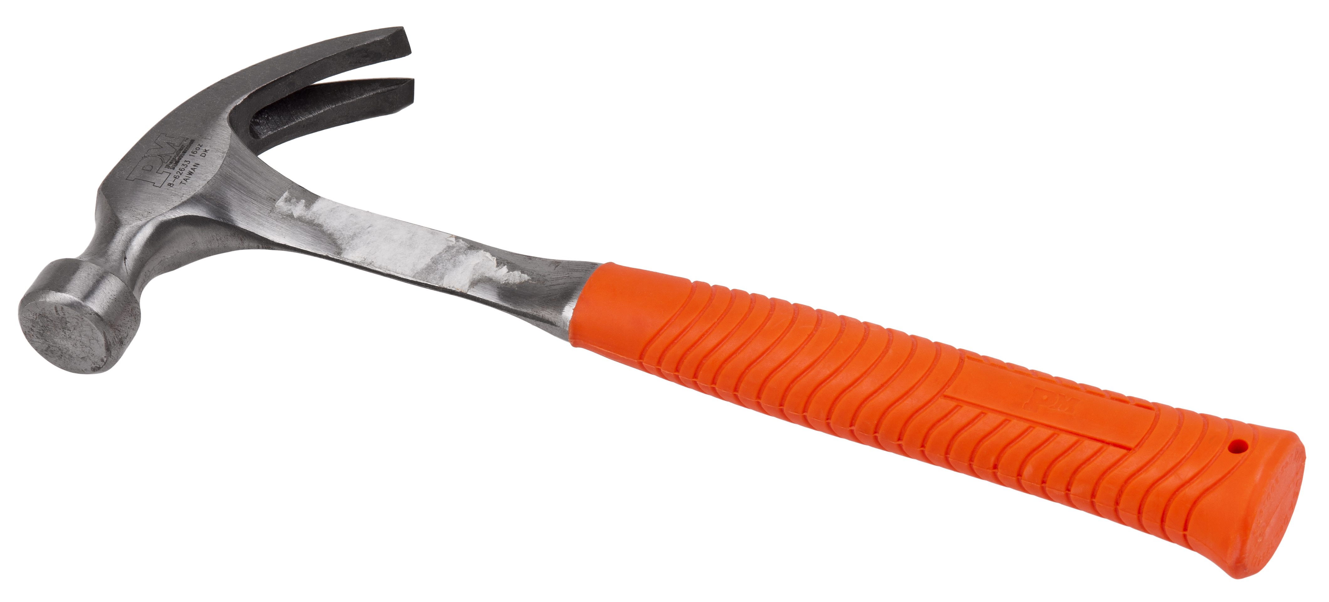
Hammer-A hammer is a tool meant to deliver an impact to an object. The most common uses are for driving nails, fitting parts, forging metal and breaking up objects.
Hardhat – OSHA approved-A hard hat is a type of helmet predominantly used in workplace environments, such as construction sites, to protect the head from injury by falling objects, impact with other objects, debris, bad weather and electric shock.
(Ratchet-type head band recommended)


Safety Glasses-Safety glasses are usually made with shatter-resistant plastic lenses to protect the eye from flying debris.
Sliding T-bevel-
A sliding T bevel is an adjustable gauge for setting and transferring angles. The handle is usually made of wood or plastic and is connected to a metal blade with a thumbscrew or wing nut. The blade pivots and can be locked at any angle by loosening or tightening the thumbscrew.

 In useThe bevel can be used to duplicate an existing angle, or set to a desired angle by using it with any number of other measuring tools
A sliding T bevel is an adjustable gauge for setting and transferring angles. The handle is usually made of wood or plastic and is connected to a metal blade with a thumbscrew or wing nut. The blade pivots and can be locked at any angle by loosening or tightening the thumbscrew.
.jpg)
Carpentry
Tool List
Maths 07/03/11
Surface Area and Perimeter of a Triangle

Surface Area and Perimeter of a Trapezoid
Surface Area and Perimeter of a Rectangle
Area and Perimeter of a Parallelogram
Area and Perimeter of a Circle
Surface Area and Volume of a Sphere
Surface Area and Volume of a Cone
Surface Area and Volume of a Cylinder
Surface Area and Volume of a Rectangular Prism
Surface Area and Volume of a Square Based Pyramid
Surface Area and Volume of a Isosceles Triangular Prism
Area of a Circle Sector
Surface Area of An Elipse
Surface Area of an Ellipse
Length of an Arc Formula
Trapezoid
Perimeter = area + b1 + b2 + c
P = a + b1 + b2 + cCircle
The distance around the circle is a circumference. The distance across the circle is the diameter (d). The radius (r) is the distance from the center to a point on the circle.
d = 2r
c = pd = 2 pr
A = pr2
(p=3.14)Rectangular Solid
Volume = Length X Width X Height
V = lwh
Surface = 2lw + 2lh + 2whPrisms
Volume = Base X Height
v=bh
Surface = 2b + Ph (b is the area of the base P is the perimeter of the base)Cylinder
Volume = pr2 x height
V = pr2 h
Surface = 2p radius x height
S = 2prh + 2pr2Pyramid
V = 1/3 bh
b is the area of the base
Surface Area: Add the area of the base to the sum of the areas of all of the triangular faces. The areas of the triangular faces will have different formulas for different shaped bases.ConesVolume = 1/3 pr2 x heightV= 1/3 pr2h
Surface = pr2 + prsS = pr2 + prs
=pr2 + prSphereVolume = 4/3 pr3V = 4/3 pr3
Surface = 4pr2S = 4pr2
Shapes Formula Rectangle:
Area = Length X Width
A = lw
Perimeter = 2 X Lengths + 2 X Widths
P = 2l + 2wParallelogram
Area = Base X Height
a = bhTriangleArea = 1/2 of the base X the height
a = 1/2 bh
Perimeter = a + b + c
(add the length of the three sides


SITE SIT OUT (14/03/11)
Step of set out of a site
Get a machine in to clean up and remove top soil.
Profiles consist of pegs, stakes or pickets, driven into the ground, with cross piece of timber attached to them.
Like formwork they are only temporary and as such they don't always look too neat, made up of all sorts of odds and ends and yet they have to contain quite a lot of information, even on a simple house extension.
They are used to transform the original pegs in the ground to something that is a semi permanent but accurate reference of the important sizes, measurements and offsets etc for a particular stage of a job. In the case above, when the concrete slab is poured the profiles can then be removed, because further measurements can be made from the actual concrete.
For the slab drawn, you may have marked on the profiles, before the excavator starts work:-
In most cases the guy on the job, say the plumber setting a floor waste or the carpenter fixing the perimeter formwork, will use a spirit level to plumb down from the string line to his job.
Many times, in sloping ground or when working in an excavation where it is hard to use a level, then the plumb bob can be very effective. I have used it in basement type situations where I simply hang the plumb line off the profile lines. I use a tie wire hook through a slip knotted loop to adjust the length of the plumb line.
A lot more convenient than straight edges and spirit levelsGetting it square.
In my opening paragraph I mentioned that mistakes in setting out can come back to haunt you. One of the classic mistakes is getting the floor plan out of square. It has repercussions for the roofer, but worse still is when you have the floor tiler in towards the end of the job and you can't escape the fact that the width of the tiles varies from one end of a wall to the other. Far easier to get it right in the setting out, right in the concrete (check the formwork before the pour) and right when laying out the internal walls.
We mainly work with rectangles in building work. A rectangle has the following attributes which help us in setting out building work.
Look at the sketch here. Let's say it is a plan of a house slab that you have to form up.
In our setting out of the rectangles in the sketch you can clearly see that each rectangle could be also seen as two triangles.
It is not good practice to use only a short section of an existing wall to get a line that is a continuation of it. Far better to try to use as much of the existing wall as possible, even if the wall has obstruction in the way. The way to do it is simple, offset the line around the obstacles.
Even if the wall is clear, using an offset is the more accurate way, because there could be local bumps in the wall that could throw your line off.
- Identify boundary link
- Determine the refrence point I .E the front or side boundary
- Vertify the location of underground and overhead service such as ( Water ,power , net , gas drain etc)
- Obtain site levels
- Vertify the position of existing structures
First checks, before you start.
- I am assuming that the relevant permits to build have been obtained.
- You should have an accurate block plan, with the lengths and angles of all the boundaries marked on it.
- Use it to check every fence line. You may have to buy or hire a long tape measure for this. I have used steel ones in the past, but they are expensive and prone to damage. I have had a 50M fibreglass one for years. It is not as accurate as a steel one (they stretch a touch) but it is indestructible.
- Every time that I have built on a boundary line (not a fence, but a proper building) I have had a certified surveyor to do a check. I just don't trust the existing fences. The very last job that I did, our surveyor pitched up an 85 to 50 discrepancy in one of the boundary walls. (The builder who put it in was a bit like me, and on the cautious side, he gave us the odd 50mm just to make sure). I could quite easily have assumed that the wall was OK and built partly on his block.
Preliminary site works.
First off tidy up the site, remove all trees that are in the way. We all love trees on our blocks, but don't try to save ones that are just too close to the new building. They are an absolute pain to work around with scaffold etc. and they usually have to go in the end anyway.- On the drawing there is always one point and one line, or two reference lines that cross one another, given to start the set out.
- Usually they are referenced to a couple of boundary lines, or an existing building.
- Go around with a few steel pegs and bang them in near enough at the corners of the proposed slab.
- From them mark out roughly the area of the job.
Get a machine in to clean up and remove top soil.
first layout
- Go around again and put in pegs for the corners more accurately this time.
- At this stage your pegs can be short wooden things that you can tap a nail in, steel rods, even screwdrivers or just besser blocks placed on the ground.
- Anything that will give you the positions of the corners.
- As you do this do checks for square. (See section on squaring below).
- At this stage, if the job is small and you getting machinery in for excavation work, you may put string lines between the pegs, and mark out the lines of trenches, or pier holes with lime.
- You could then get the excavation work done first, before going on to the next stage.
Profiles, batter boards or hurdles.
 |
| Setting out - A plan of a concrete slab showing the profile positions. |
Profiles consist of pegs, stakes or pickets, driven into the ground, with cross piece of timber attached to them.
Like formwork they are only temporary and as such they don't always look too neat, made up of all sorts of odds and ends and yet they have to contain quite a lot of information, even on a simple house extension.
 |
| Setting out - A 3D view showing the use of profiles on the above slab. |
They are used to transform the original pegs in the ground to something that is a semi permanent but accurate reference of the important sizes, measurements and offsets etc for a particular stage of a job. In the case above, when the concrete slab is poured the profiles can then be removed, because further measurements can be made from the actual concrete.
For the slab drawn, you may have marked on the profiles, before the excavator starts work:-
- The position of all the foundations, for external and internal walls.
- The wall positions to let the plumber accurately to position his sewerage pipes and floor wastes. To let the concretor place wall starter bars in the slab or column HD bolts.
- Possibly underground power supply and entry point.
- The first trade to use the profiles will be the excavator, so a reasonable clearance between the work and the profile itself is needed, to allow the machine to do it's job without squashing a hurdle her of there.
- In the sketches shown here I have shown them marked out with the overall sizes of a concrete slab.
- They could just as easily have a set out for the width of excavation trenches etc.
- Quite often a profile may consist of a board nailed to an existing boundary fence. There is no absolute rule, just something that can be marked out, take a nail or a screw and is fairly robust so it can't get moved out of position easily.
 |
| Setting out - A hurdle or profile used for setting out. |
In most cases the guy on the job, say the plumber setting a floor waste or the carpenter fixing the perimeter formwork, will use a spirit level to plumb down from the string line to his job.
Many times, in sloping ground or when working in an excavation where it is hard to use a level, then the plumb bob can be very effective. I have used it in basement type situations where I simply hang the plumb line off the profile lines. I use a tie wire hook through a slip knotted loop to adjust the length of the plumb line.
A lot more convenient than straight edges and spirit levelsGetting it square.
In my opening paragraph I mentioned that mistakes in setting out can come back to haunt you. One of the classic mistakes is getting the floor plan out of square. It has repercussions for the roofer, but worse still is when you have the floor tiler in towards the end of the job and you can't escape the fact that the width of the tiles varies from one end of a wall to the other. Far easier to get it right in the setting out, right in the concrete (check the formwork before the pour) and right when laying out the internal walls.
We mainly work with rectangles in building work. A rectangle has the following attributes which help us in setting out building work.
- Each of the four angles is 90 degrees, or square as we call it.
Great, this means that if we have a base line side set up, and then get a second line set up off it at the right spot, at 90 degrees to the first we have two of our side done. - The opposite sides are parallel, that is, they are the same distance apart.
That is it! Measure the correct length from one end of the first side and the same length from the other end and we have our third side fixed. Do the same again and we have our fourth side. That could be it - finished. - The diagonals are equal lengths. That is the length from one set of opposite corners is the same or equal to the length from the other set. This means that if we have got a touch out with either of the first two steps (as you do:-), we have an excellent way of checking our set out
 |
| Setting out - Using a 3,4,5 triangle |
Look at the sketch here. Let's say it is a plan of a house slab that you have to form up.
- You should first have an idea of which will be the most important side, that the rest are made square and parallel to it.
- Split it into rectangles and check the diagonals for equal. The dotted red lines.
In our setting out of the rectangles in the sketch you can clearly see that each rectangle could be also seen as two triangles.
- Two thousand five hundred years ago the ancient Greek philosopher and mathematician Pythagoras discovered his truths about right angle triangles.
- Anyone with a cheap student's calculator can use Pythagoras' theorem to get the length of the diagonal side if you know the lengths of the other two sides. (The sum of the squares of the two shorter sides is equal to the square of the other).
- There is a unique triangle that is often used to demonstrate this principle, 3,4,5. ( (3x3=9)+(4x4=16) 9+15=25, so does 5x5=25)
- So any triangle in this ratio, will have a 90 degree corner opposite the long side.
- Ratio is the key word.
- The units don't matter as long as the ratio is the same.
- 3,4,5 miles, or 3,4,5 centimeters, the right angle is still there.
- So If we are looking at a house plan in the sketch above, I could use say 2M as my unit.
- I would bang a nail in the formwork 8M (that is 4units of 2M each) from the bottom right hand corner.
- Another one would go in at 6M (3units of 2M) along the other edge.
- I would check the distance with my long tape between the two nails and if it was within 5mm of the 10M (5units at 2m) that I was expecting, I would modestly say to my offsider, "crikey we were lucky there mate".
- If it was a bit more out like 40mm or so then I would move the nail holding my string line on the profile to correct the error, and then work from the altered line, thinking myself lucky that I had checked the set out before we had done a lot m
Offsets
 |
| Setting out - Offset line around obstacles. |
It is not good practice to use only a short section of an existing wall to get a line that is a continuation of it. Far better to try to use as much of the existing wall as possible, even if the wall has obstruction in the way. The way to do it is simple, offset the line around the obstacles.
Even if the wall is clear, using an offset is the more accurate way, because there could be local bumps in the wall that could throw your line off.
- In the sketch above I show a method of using the profile to offset the line to miss obstacles and then reset to get the point that is a true extension of the main building line.
- I want to mark out, on my profile (to the left), a building line for a new extension, that is exactly a straight continuation of the main house wall.
- I just pick a distance from the house that gets me clear of the various obstructions. In this case it is 145mm.
- I make sure the string line is offset the same distance from the house,and then I put a nail or a screw into my profile at the continuation of that line. That is I place a line parallel to the wall 145 off it.
- I then measure back the offset distance to get a point exactly in line with the wall.
- I bang a nail into a brick joint or a peg touching the wall, and string a line, shown dashed, to fix the true building line.
Subscribe to:
Posts (Atom)